60 Second Timer
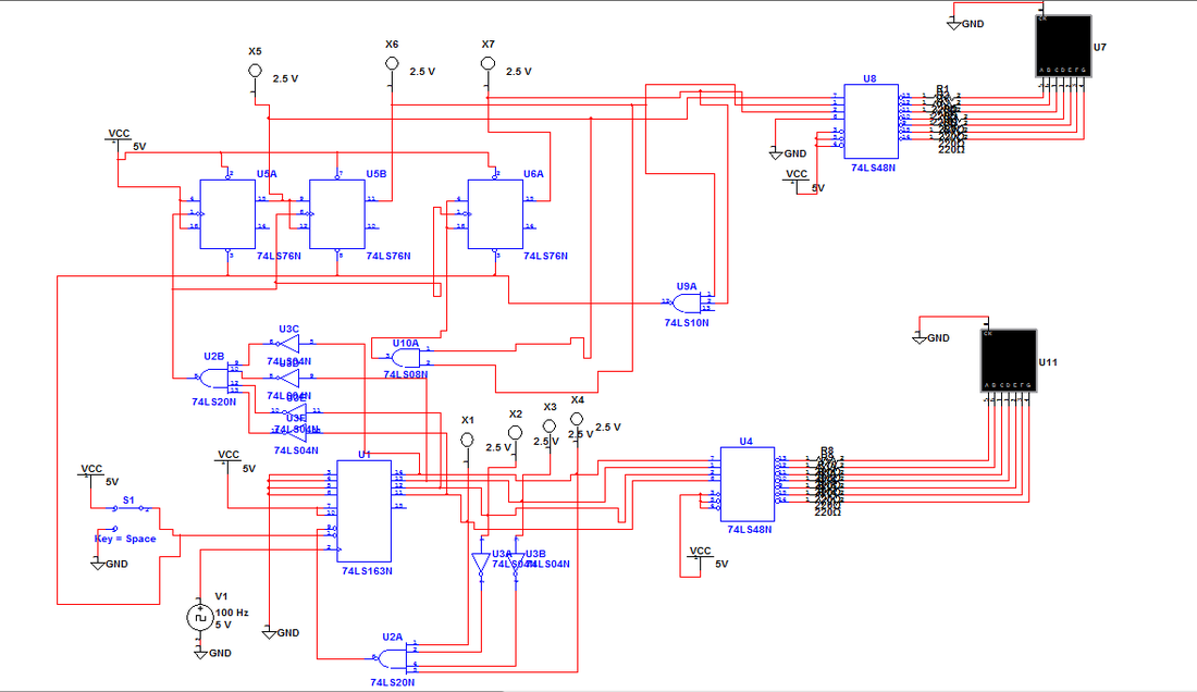
To follow up from our now serving display, we were tasked to design, implement and test a timer that would count up from 0 to 60. It would have two inputs that would be limited to a clock and reset button. The goal was for the timer to reach 60 and then loop back around to 0. We continued past concepts by learning more themes and further implementation techniques of flip-flops and synchronous counters.
Circuits:
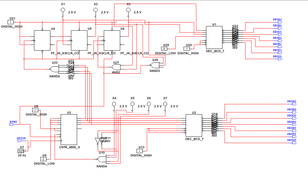
PLD:
Conclusion:
In this project, we designed, implemented, and tested a simple yet thoroughly entertaining digital sixty second timing device, similar to that of a digital watch or clock. We were told to make a virtual PLD and non-PLD circuit representation of this sixty second timer through Multisim and then show that our design works by testing it on an actual PLS board. At first, I started on the regular circuit and ran into some difficulties. But, these were not long lasting as I soon finished my regular, non-PLD circuit. Then, I moved on the PLD circuit which was essentially a cop-paste of our other circuit. But, because this was PLD mode we had to replace certain parts with their PLD counterparts. For example, buttons and seven-segment displays are implemented differently in the two modes. While implementing the PLD circuit, I once again ran into some difficult, challenging, and complex obstacles. Some of these were simple, like wires that appeared to be connected, but in reality were not. However, the more interesting puzzles were more enjoyable to solve. For example, I initially lacked space to place my probes and because certain sections of my circuit were so crowded, I could place new components without them getting connected to older tones that I didn’t want them to be connected to. To resolve this, I started experimenting with multiple-selection move, cut, copy, and paste option. I learned a lot about Mulitsim’s features through this project. This project was very entertaining and fun, and built upon what I already knew about synchronous counters and flip-flops.
